
Ultrafast laser technology enables internal engraving in glass
Industrial Lasers Solutions for manufacturing – published November 1st 2018 – Article written by ROBERT BRAUNSCHWEIG and DAVID BRUNEEL
Process allows for improved traceability of glass medical devices
Femtosecond laser technology applied in glass is used in various fields. For example, marking in glass allows the traceability of syringes or other devices made of glass, which represents a huge market in the pharmaceutical and medical fields.
Recognizing this, femtosecond laser machine maker Lasea and its partners have developed a non-aggressive internal engraving laser system (NAGINELS) process to mark diffractive data matrices inside glass-based syringes without cracks and that can be read by an external instrument.1,2 Patented in 2008, the technology can also be applied to different types of glasses. This article describes the process principle and the validation process in terms of reading and quality control, and provides associated industrial solutions.
Physical principle
When a femtosecond laser interacts with glass, structural modifications and a volume variation occur at the focus point, leading to colored centers, refractive index variation, and induced stress in and around the laser-affected zones. These effects depend on laser parameters such as pulse energy and energy deposition. For instance, energy deposition Ed is calculated according to the scan speed, the pulse energy, the repetition rate, and the spot size at the focus point as summarized below:

where Ep is the pulse energy, f is the repetition rate, W is the spot diameter, and v is the scanner speed.3
FIGURE 1 illustrates these effects on glass while increasing the energy deposition. The pattern consists of a square area filled with parallel lines inscribed in glass and spaced by a few tens of micrometers to obtain a diffractive effect.
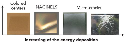
FIGURE 1. Effects at the focus point after femtosecond laser irradiation are shown.
At low energy deposition, colored centers form and are not permanent. Indeed, after a few weeks or by heating the structures, these colored areas disappear. This is because of the deposited energy being not sufficient enough to break atomic bonds and, after a certain time or with the help of the heat, the material returns to its original state. When the energy deposition increases, permanent structures form and volume variation creates a refractive index variation. Managing these variations, we create diffractive structures. At higher energy, micro-cracks start to form and propagate, which can lead to breaking the entire piece of glass.
From these results, laser parameters can be defined to engrave diffractive gratings and prevent crack formation. Data matrices have a square shape made of cells to stock information. The number of cells is chosen according to the quantity of information that we want to write. Each cell is made of a grating. The diffractive effect needs to have a sufficient contrast for the marks to be read and decoded.
Systems used for the process
An air-cooled femtosecond laser emitting in the infrared (IR) is focused in glass by a special lens mounted on the scanner head to mark the lines. A beam shaping system is used to adapt the beam before the scanner head, allowing adjustment of the spot size. The scanner head moves the beam in the sample at a very high speed. FIGURE 2 shows the typical writing setup.
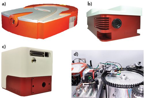
FIGURE 2. Elements used for the process include the Satsuma air-cooled femtosecond laser from Amplitude Systèmes (a), the LS-Shape special beam shaper from Lasea (b), the LS-Scan high dynamic scanner from Lasea (c), and turn wheel for handling and control from Lasea (d).
After defining the laser parameters for a new type of glass, validations on thousands of syringes must be done to check for the lack of micro-cracks. To do so, we take pictures with a 10X confocal microscope. FIGURE 3 illustrates an example of a data matrix image.
FIGURE 3. An example of a grating inscribed in a syringe is shown.
A range of energy deposited is tested and a security margin is defined. Additional tests (for example, crush and vision tests) are then done by Lasea’s customers to verify the syringe integrity impact.
Data matrices made of gratings are illuminated with a lamp under a given angle, so that the light is diffracted when passing through the gratings. A camera takes a picture of the illuminated data matrix and a software or application decodes the information. FIGURE 4 shows an example of illuminated data matrices with white light and blue LEDs.
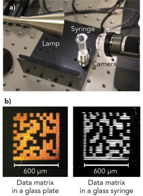
FIGURE 4. The decoding system (a) and examples of illuminated data matrices (b) are shown.
An automated system combining those elements can be integrated in a machine with different sources and cameras. The lighting and camera are then optimized to get a Grade 4 on all high-speed readings (up to 600 syringes/min).
Industrialization
The laser parameters and scanner parameters are set using Kyla, Lasea’s micromachining software. Any machine can integrate these elements, adapted according to the application. For instance, we have developed machines combining a wheel on which syringes are fixed and synchronized with the scanner mirror’s movements (FIGURE 5). The wheel turns in front of the scanner and a trigger allows marking on-the-fly as each syringe passes through the scanner field. Nesting and denesting systems can be added before and after the marking process.
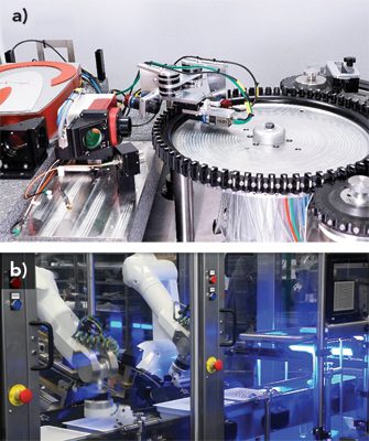
FIGURE 5. The NAGINELS marking system (a) and denesting system (b) are shown.
FIGURE 6 shows an example of a marked syringe—a data matrix is written in the syringe and illuminated with white light.
FIGURE 6. An example of a marked syringe is shown.
Conclusion
Lasea and its partners have developed a process to mark syringes or other glass-based devices for traceability. This process can also be used for decoration since diffractive structures are printed. Laser parameters can be controlled for the diffractive effect and avoid crack formation, which is very important in the pharmaceutical industry. Indeed, liquid inside a syringe will be injected into the human body, so particles of glass are unacceptable. Most importantly, this process is currently being industrialized and implemented with Lasea’s capabilities at Sanofi-Pasteur, a major pharmaceutical company.
ACKNOWLEDGEMENTS
The author would like to thank Axel Kupisiewicz, CEO and founder, and Audrey Champion, project engineer – R&D, both from Lasea SA (Angleur, Belgium); Paul-Etienne Martin, general manager of Lasea France (Pessac, France); Eric Mottay, CEO of Amplitude Systèmes (Pessac, France); and Teddy Klein, global engineering – technology program leader at Sanofi-Pasteur (Lyon, France), for their contributions to this article.
REFERENCES
1. J. Remits, “Des gravures invisibles et anti-contrefaçon,” Trends-Tendances, 84 (Jan. 10, 2008).
2. Project supported by the European Commission “Naginels” (COOP 512931) with the following partners: Lasea, Amplitude Systèmes, Costet, TBS, and ALPhANOV.
3. S. Rajesh and Y. Bellouard, Opt. Express, 18, 20, 21490–21497 (2010); doi:10.1364/oe.18.021490.
ROBERT BRAUNSCHWEIG (rbraunschweig@lasea.com) is general manager and vice president of U.S. sales for Lasea Inc., El Cajon, CA; www.lasea.com, while DAVID BRUNEEL is processing and modeling unit manager of the R&D department at LASEA SA, Angleur, Belgium.
Source: tinyurl.com/y88fz7er